
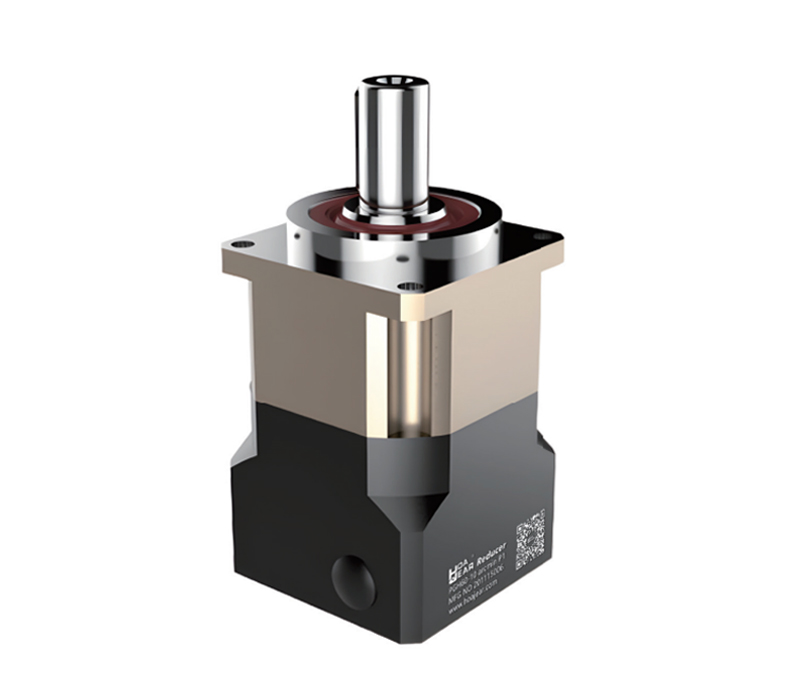
A Planetary Gear Reducer is a mechanical transmission that reduces rotational speed and increases available output torque through a compact arrangement of gears. It connects a motor to a driven mechanism, helping match motor performance to the speed and load requirements of industrial equipment.
For machine builders, a planetary gear reducer offers a useful combination of compact dimensions, torque capacity, and positioning performance. A correctly selected planetary gear reducer can support smooth acceleration, controlled stopping, and reliable operation in demanding automation cycles. Understanding how a planetary gear reducer works makes it easier to compare specifications and avoid selection mistakes.
Inside a planetary gear reducer, four elements form the basic transmission: the sun gear, planet gears, ring gear, and planet carrier. The sun gear sits at the center. Planet gears surround it and mesh with both the sun and the internal teeth of the ring gear.
The carrier supports the planet gear shafts and transfers their combined movement to the output. Bearings, seals, lubricant, and the housing complete the assembly. In a typical planetary gear reducer, the ring remains stationary while the sun receives motor power. The construction of a planetary gear reducer allows several gear meshes to transmit load simultaneously.
When the motor turns the sun gear, each planet rotates around its own axis while traveling around the sun. Because the ring gear is fixed in this common arrangement, the planets drive the carrier at a lower speed than the input.
The carrier becomes the output of the planetary gear reducer. This slower output provides higher torque, subject to transmission losses and mechanical ratings. A planetary gear reducer does not create additional power; it exchanges speed for torque. Although other planetary arrangements exist, a motor-driven planetary gear reducer commonly uses sun input, fixed ring, and carrier output.
For the fixed-ring arrangement described above, the planetary gear reducer ratio is calculated as:
Reduction ratio = 1 + (ring gear teeth ÷ sun gear teeth)
If the ring has 60 teeth and the sun has 20 teeth, the ratio is 4:1. With an input speed of 3,000 rpm, the theoretical output speed is 750 rpm.
A planetary gear reducer with a higher ratio produces a slower output for the same motor speed. However, the available ratio depends on gear geometry and stage arrangement. When selecting a planetary gear reducer, confirm both the required output speed and the motor speed necessary to achieve it.
The approximate output torque of a planetary gear reducer can be estimated using:
Output torque = input torque × reduction ratio × efficiency
For example, assume 10 Nm input torque, a 4:1 ratio, and 95% efficiency. The estimated output torque is 38 Nm. The efficiency is an illustrative assumption, not a universal product specification.
A planetary gear reducer must still remain within its permitted output torque. Continuous torque, acceleration torque, and emergency loads require separate checks. Installing a larger motor does not automatically allow a planetary gear reducer to transmit more torque than its gears, shafts, and bearings can withstand.
A single-stage planetary gear reducer uses one planetary gear set. A multistage planetary gear reducer connects two or more sets in sequence, allowing greater overall speed reduction within a relatively compact assembly.
Stage ratios multiply. Two stages with ratios of 4:1 and 5:1 produce a total ratio of 20:1. However, additional stages introduce more transmission losses and may affect length, inertia, and backlash. Choosing a planetary gear reducer therefore involves more than finding the largest ratio. The appropriate stage count depends on output speed, torque demand, installation space, and positioning requirements.
The coaxial arrangement of a planetary gear reducer places the input and output on the same centerline in an inline design. This can simplify motor mounting and help fit transmission components into restricted machine spaces.
Several planets share the transmitted load, supporting high torque capacity relative to gearbox size. Actual load sharing depends on manufacturing accuracy, stiffness, and assembly quality. A planetary gear reducer should therefore be evaluated using verified ratings rather than appearance alone. A compact planetary gear reducer can still require substantial support structure when acceleration, overhung loads, or repeated reversals are involved.
A planetary gear reducer may use spur or helical gearing. Spur gears have straight teeth and relatively simple geometry. Helical gears engage progressively, which can help reduce running noise and improve smoothness under suitable operating conditions.
Helical gearing also introduces axial forces that the bearing system must accommodate. Neither tooth form guarantees superior performance in every machine. When comparing a planetary gear reducer, review measured noise, torque capacity, backlash, bearing arrangement, and operating speed together. The overall design and manufacturing quality of a planetary gear reducer matter more than a single construction feature.
Backlash is the angular clearance noticed when transmission direction reverses. A low backlash planetary gear reducer can reduce lost motion in applications involving frequent changes of direction. Backlash is commonly specified in arcminutes, with 60 arcminutes equal to one degree.
However, a planetary gear reducer also twists elastically under load. This behavior depends on torsional stiffness and is different from backlash. Encoder accuracy, coupling compliance, machine structure, and thermal changes also influence positioning. Selecting a planetary gear reducer solely by its backlash value can overlook larger sources of error elsewhere in the motion system.
A planetary gear reducer changes the load inertia reflected to the motor. For an ideal rigid transmission, reflected load inertia equals output load inertia divided by the square of the reduction ratio.
At 4:1, a load inertia of 0.016 kg·m² reflects approximately 0.001 kg·m² to the motor, before adding transmission inertia. A planetary gear reducer can therefore help match a large load to a motor. Nevertheless, a planetary gear reducer also adds its own inertia, friction, and compliance. Check acceleration torque, motor speed, and settling behavior before assuming that increasing the ratio improves control.
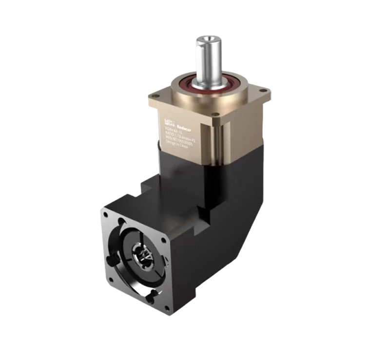
A planetary gear reducer is used in packaging machinery, automated assembly, material handling, printing equipment, and motion axes. Typical tasks include driving conveyors, rotating fixtures, feeding material, and positioning mechanisms through repeated production cycles.
In a packaging machine, a planetary gear reducer may drive a feed roller that accelerates and stops repeatedly. In an assembly station, it may rotate a fixture between working positions. Each application places different demands on the transmission. A planetary gear reducer selected for steady conveyor operation may require different torque margins and precision characteristics from one used for rapid indexing.
Start planetary gear reducer selection with the actual motion cycle: load, speed, acceleration, deceleration, operating time, and stopping frequency. Calculate the torque required to overcome process resistance and accelerate the moving components.
Next, check the planetary gear reducer against continuous, cyclic, peak, and emergency torque limits using the supplier’s rating definitions. For thermal assessment, follow the specified duty-cycle calculation rather than applying an unsupported average. Confirm input speed limits and expected operating temperature. A planetary gear reducer that survives a brief torque peak may still be unsuitable for continuous production if its thermal capacity or bearing life is insufficient.
Output torque is only one loading condition for a planetary gear reducer. Belt tension, pulley weight, gear engagement, and suspended fixtures can impose radial or axial forces on the output bearings.
The distance between the applied force and the bearing support also matters. Moving a pulley farther from the housing increases bending moment even when belt tension remains unchanged. Before installing a planetary gear reducer, compare the actual force location with the conditions used in its load rating. Some applications need external bearing support so the planetary gear reducer transmits torque without carrying excessive structural loads.
Before mounting a planetary gear reducer, verify motor flange dimensions, shaft diameter, shaft length, and coupling compatibility. Clean the mating surfaces and follow the specified assembly sequence, fastener torque, and clamping instructions.
Do not force a motor shaft into a misaligned input coupling or hammer components onto the output. These actions can damage bearings and disturb alignment. A planetary gear reducer also needs a rigid mounting surface that resists movement under load. After assembly, run the planetary gear reducer at low speed and check rotation direction, noise, vibration, and fastening before increasing load.
Lubrication separates contacting surfaces and limits wear within a planetary gear reducer. The required grease or oil depends on gearbox design, speed, load, mounting position, and ambient conditions. Follow the specified lubricant type and quantity.
Some models are factory lubricated for their defined service conditions; others require scheduled maintenance. A planetary gear reducer should not automatically be treated as maintenance-free. Monitor temperature trends after installation and during production changes. If a planetary gear reducer becomes progressively hotter under an unchanged duty cycle, investigate lubrication, alignment, overload, bearing condition, and cooling around the housing.
Unusual symptoms in a planetary gear reducer can originate inside the gearbox or elsewhere in the machine. Loose mountings, coupling misalignment, excessive acceleration, and servo tuning can produce vibration that resembles internal gear damage.
Record when the symptom occurs: during acceleration, steady running, reversal, or stopping. Compare the planetary gear reducer at similar speed and load before drawing conclusions. Leakage requires inspection of seals, lubricant quantity, and operating conditions. If a planetary gear reducer develops sudden noise, excessive play, or rapidly increasing temperature, stop the machine safely and identify the cause before restarting.
A planetary gear reducer is one option among worm, parallel-shaft, cycloidal, and strain-wave transmissions. Each has different strengths, limitations, ratios, and installation requirements. Compare complete drive arrangements under the same operating conditions.
An inline planetary gear reducer is often attractive when coaxial mounting, compact size, and servo compatibility are priorities. Other designs may suit a required shaft arrangement or specialized reduction ratio. Do not assume a planetary gear reducer provides self-locking. Where a vertical load must remain supported after power loss, evaluate a suitable holding brake and the complete load-holding arrangement.
For acceptance testing, record output speed, cycle time, stopping error, housing temperature, and abnormal vibration under representative operating conditions. Test repeated reversals and the heaviest planned load rather than relying on unloaded operation. Keep these measurements as a baseline for maintenance. Where positioning is critical, measure movement at the driven mechanism because motor feedback alone cannot reveal every source of mechanical error in the assembly.
Yes, if its input interface and ratings match the motor. A planetary gear reducer still requires checks for acceleration, speed, load inertia, and positioning performance.
No. A planetary gear reducer increases available output torque by reducing speed. Output mechanical power is lower than input power because of transmission losses.
No. A planetary gear reducer must have appropriate backlash, stiffness, torque capacity, and installation quality for the application. Precision requirements should be quantified before selection.
Many designs support both directions, but reversal frequency and loading affect selection. Confirm the permitted operating conditions for the specific planetary gear reducer.
A planetary gear reducer works by combining sun, planet, ring, and carrier motion to provide controlled speed reduction and torque multiplication. Its performance depends on the complete mechanical design and operating conditions.
To specify a planetary gear reducer, prepare the motor details, output speed, load torque, duty cycle, accuracy target, and installation drawing. These inputs support a practical technical review and help identify a transmission that matches the machine’s production requirements.
QR Code


Este sitio web utiliza cookies para garantizar que obtenga la mejor experiencia en nuestro sitio web.


 EN
 Pусский
 Indonesia
 Tiếng Việt


 Whatsapp
 Teléfono
 E-mail
 mensaje
Comentario
(0)